

Formula E - Racing into the future
Date: Oct 18, 2018
Author: Phillip Abplanalp, Hardware Engineer
Introduction
Motor racing with the absence of screaming engines and grid girls would have been a recipe for catastrophe only 20 years ago. But here we are, 2018, and this is exactly what Formula E (FE) offers and it seems be working, really well in fact – although it seems the removal of the grid girl has resulted in quite a saga! For those that may have missed the memo, Formula E is a single seater, fully electric racing series, competing at a range of street circuits around the globe. Started in 2014, it’s seen a rapid growth in both viewership and automotive manufacturer interest. Approaching its 5th season, FE boasts a staggering number of automotive manufacturer entries including: BWM, Audi, Nissan (Renault group), DS Automobiles (Citroen-Peugeot group), Mahindra (large Indian car company) and Jaguar. Two further mega manufacturers are set to join at the end of 2019 - Porsche and Mercedes. For this reason we at Beta Solutions thought it was high time that we take a deeper look at what all the commotion is about!
What is a Formula E car?
Looking at the exterior of a FE car, a lay person would be forgiven for confusing it with almost any other single seater formula car. With the typical single seater concoction of front and rear wings, open cockpit, central roll hop and radiators, these are all features synonymous with those of say a Formula One car. However, even here the under lying philosophies of the car's aerodynamics are actually significantly different. Whereas the aerodynamic surfaces on Formula One cars are primarily designed to generating copious amounts of downforce (at the expense of drag), FE is far more focused on reducing drag (at the expense of less downforce). These differences in aerodynamic philosophies stem from the very core of the FE series - its energy storage medium and the need to preserve energy.
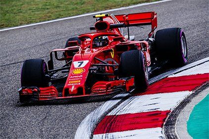
Figure 1: 2018 Ferrari Formula 1 Car
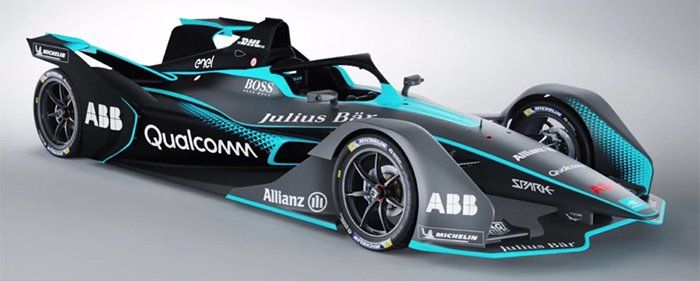
Figure 2: 2018-2019 Formula E Car
But as the old adage goes, it’s what’s inside that counts, right? So what's under the skin of a Formula E car? Read on ...
Essentially a FE car is a battery powered electric vehicle which is made up of four critical electrical components, these are set out below:
Electric Motor/Generator
This component is responsible for both propelling the car under acceleration and recovering energy under braking. Typically the motor/generator is some configuration of a Permanent Magnet Synchronous Motors (PMSM) - which is in essence a permanent magnet 3-phase AC (Alternating Current) motor – similar also to Brushless DC (Direct Current) motors. This section of the regulations are open to all teams to develop and try find the most optimal solution.
Inverter
This component takes in the DC current supplied from the battery and turns it into a 3-phase AC used to drive the motors, as well as controlling the motors speed based on the input from the driver. The Inverter, like the electric motor/generator, is open to development.
DC to DC Converter (power supply)
The DC to DC power supply is responsible for converting the 500 VDC (Gen 1 battery voltage) to a more usable voltage range such as 12-16 VDC (McLaren MCU-5001) for all the auxiliary components like the numerous sensors on the car or steering wheel computer. Some inverters (such as McLaren MCU-500) will include both the DC to DC power supply & inverter all as one single component.
1 McLaren MCU – 500 is an example of an Inverter similar to those used on an FE car. The exact components are not publicly available.
Battery
The battery is the component which stores electrical energy which the car uses throughout the race to both propel it and also power the numerous on board sensors. This component is a “standardised” part that is provided by an FIA (Fédération Internationale de l'Automobile) selected manufacturer. For the first four seasons, the battery pack was supplied by Williams Advanced Engineering and from season five it will be supplied by McLaren Applied Technology.
The diagrams below show a high level representation of the interconnection of the components discussed above.
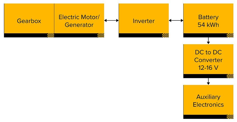
Figure 3: High level system diagram – Gen 2 Formula E car.
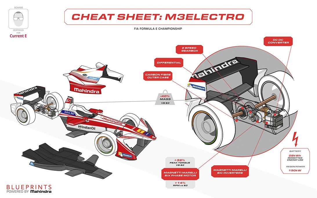
Figure 4: Gen 1 car with showing the general layout packaging.
Formula E Technical Evolution
As part of the 5th season of FE, the series is rolling out its second generation (Gen 2) car. Along with some exterior cosmetic changes to the body work, the cars have undergone a significant overhaul of some of the key technical areas. The most significant of these changes are outlined in the table below as follows:
Note: At the time of writing, the full FIA Technical regulations for 2018-2019 had not be made public.
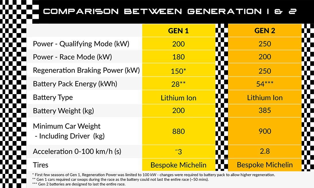
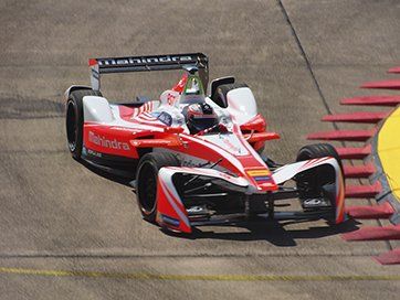
Figure 5: Gen 1.
Figure 6: Gen 2.
Perhaps the most significant change between Gen 1 and Gen 2 cars is the removal of the in race ‘car change’. Under the Gen 1 regulation (first four seasons) it was mandatory for all drivers to make a ‘car change’ pit stop which required drivers to change from a FE car with a depleted battery to a new fully charged FE car. This was essentially due to the Gen 1 battery pack (at 28 kWh) not being large enough to last an entire race (~50 mins) and the swapping of batteries during the race were deemed to be too dangerous and complex. To allow the Gen 2 FE cars to last an entire race on a single charge the battery capacity has been raised from 28 kWh to 54 kWh. While it is great to have had such a large energy capacity increase, the knock-on effect has been an increase in the battery pack weight from ~200 kg (Gen 1) to 385 kg (Gen 2). This unfortunately means the overall energy density of the battery packs have only slightly increased over the intervening 5 years2!
2 Gen 1 = ~ 140 Wh/kg to Gen 2 = 140.2 Wh/kg
Possibly the second largest change being implemented for the Gen 2 regulations is the increased power allocation for regenerative braking. Regenerative braking power limit essentially determines the amount of energy that can be recovered during a braking phase, the higher the amount set by the regulation means less wasted energy and therefore an increased overall system efficiency. The Gen 2 regulations will allow an increased regeneration power of more than 60% over the previous Gen 1 cars, going from 150 kW to 250 kW. Interestingly enough under racing conditions this will mean that the Gen 2 cars will for the first time have the ability to recover/regenerate energy at a higher rate than what is allocated for acceleration (250 kW (regenerate) vs 200 kW (accelerate)). Perpetual motion, right? Not quite, but it’s likely to allow for energy recover in the range of ~1 kWh (~3.6 Mj) per lap, potentially meaning that as much as 50% of the used energy is being recovered over the lap3.
3 Calcs are based on a 100 s lap, 15 s braking duration per lap at the full 250 kW recovery during the entire braking phase, 50 min race length and 54 kWh battery.
Technology Transfer – From the Race Track to the Road
Over the past decade the development of road relevant technology on the race track has become somewhat of the holy grail for motor sport regulators. This has become increasingly important as society demands motor sport to be not just entertaining but also environmentally sustainable! Sustainability in the context of motor sport has to be automotive manufacturers using it as a tool for developing the road cars of tomorrow.
So, if the vision is to assist with the development of future electric vehicles, how is FE doing? Well in my opinion, both good and bad (or should that be positive and negative!). Perhaps on the bad side is the closed nature of the existing FE regulations for arguably the most important component to the success of electric vehicles. This of course is the battery, and more importantly their present lack of energy density. For a number of reasons including to limit excessive spending, stopping runaway scenarios (where one team has gained a significant advantage) and to encourage development in other areas the FIA (FE regulators) have opted for “standardised” batteries for FE. This means an identical battery is supplied to all teams, not allowing individual teams to try develop their own optimised solution. However without a high level of competition in this area, the development of the batteries in FE is likely to show very little progress and this is already visible with essentially zero gains to energy density having been achieved over the 5 seasons of FE! If you are thinking energy density isn’t that big a deal, consider for comparison, the energy density of these batteries compared with petroleum powered combustion engines. Namely, the battery packs on these Gen 2 FE cars will have energy densities of only ~1% of that of petroleum4! This is a gigantic difference and even when considering the potential for energy recovery and the significant efficiency differences between a combustion engines and electrical equivalent (20-35% vs 80-90% respectively) the total energy storage for an electrical system is still likely to be ~30x heavier to do the same work. What’s more disappointing is that the regulations are unlikely to allow any battery development by teams until at least 2025. So, if you are after the state-of-the-art in battery technology it is unlikely that this will be found in FE before 2025!
4 petroleum=~12.8 kWh/kg and Gen 2 Battery = 0.14 kWh/kg
On the good side, is that the present regulations are very open on the drive train and power electronics of the car with both the electric motor and the inverters being free to develop. With teams partnering with the likes of semiconductor giant Rohm, significant gains have be made on both the physical packaging size, weight of the inverters and a reduction in energy losses. These gains can be seen in the image below:
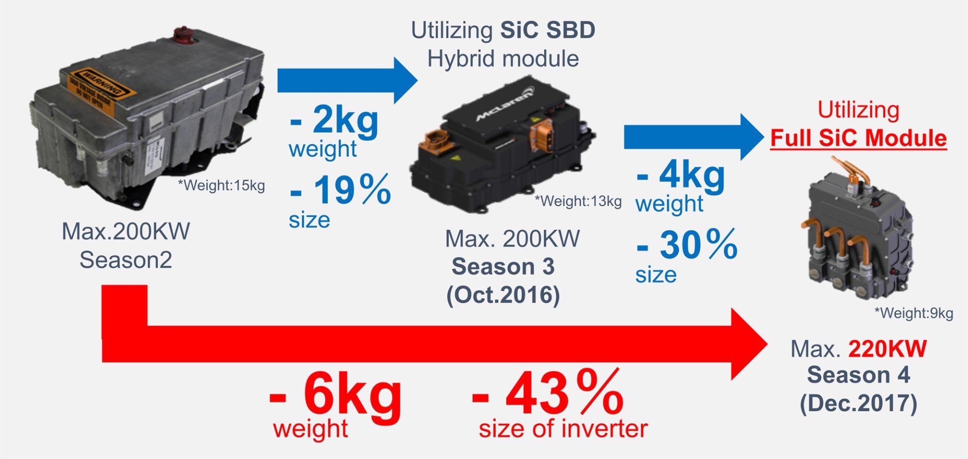
Figure 7: Design evolution of inverters.
These improvements have in large come from the developments Rohms has made in the area of silicon carbide (SiC) MOSFETs used for the switching of the inverter. These developments have been implemented in a two stage implementation, starting in season 3 with a hybrid solution of standard silicon IGBTs (Isolated Gate Bipolar Transistor) but SiC based Schottky Barrier Diodes (SCB) rather than the conventional pure silicon based diodes. SiC Schottky Barrier Diodes offer reduced reverse leakage (at high switching frequencies) through faster reverse recovering times and also reduced package size, resulting in the inverter being having lower switching losses and reduced size and weight. Season four saw the implementation of full SiC modules with both SiC MOSFET and Schottky Barrier Diodes, bringing further reduction in high speed switching losses, resulting in increased efficiency and smaller packaging. See overall switching gains in Figure 8 and a Half Bridge SiC Module in Figure 9 below:
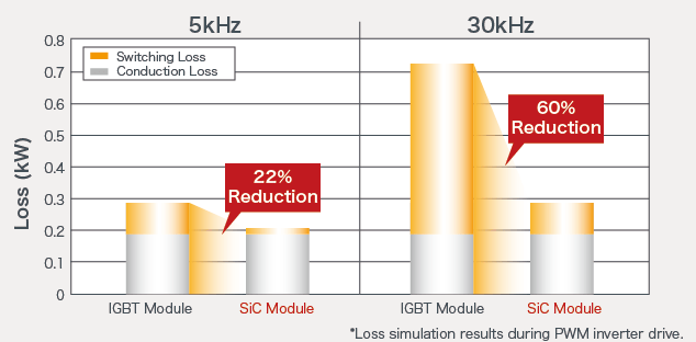
Figure 8: SiC MOSFET Reduction in switching losses vs IGBTs.
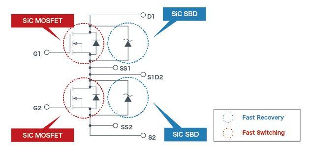
Figure 9: Half bridge using SiC MOSFETs and Schottky Barrier Diodes.
Conclusion
While there are improvements to be made to the series such as opening battery development, it is a racing series with a positive future and one that is rapidly gaining traction, both with fans and manufacturers! So be sure to join the electrification movement and tune into the first race of season 5 on the 16th of December (2018).
Feel free to pop in for a coffee and join our lively discussions about the technology and the driving strategies as the seasons progress.
References:
- Figure 1, 2018 Ferrari Formula 1 Car Retrieved from https://formula1.ferrari.com/en/2018-f1-chinese-gp-free-practice-1/
- Figure 2 and Figure 6, 2018-2019 Formula E Car. Retrieved from http://formula-e.wikia.com/wiki/Spark_Gen_2
- Figure 4, Blueprints Powered by Mahindra. Retrieved from https://current-e.com/blueprints/powertrain-explained-m3electro/
- Figure 5, Gen 1 - Felix Rosenqvist at the 2017 Berlin ePrix. Retrieved from https://en.wikipedia.org/wiki/Formula_E
- Figure 7, Design evolution of inverters. Retrieved from http://micro.rohm.com/en/formulae/sic.html
- Figure 8, SiC MOSFET Reduction in switching losses vs IGBTs. Retrieved from https://www.rohm.com/sic/full-sic-power-modules
- Figure 9, Half bridge using SiC MOSFETs and Schottky Barrier Diodes. Retrieved from https://www.rohm.com/sic/full-sic-power-modules
- Vector Racing Flags Illustrations by https://www.vecteezy.com/
- Vector of Racing Car Layout https://www.vecteezy.com/
- Vector of E Graphics by: https://www.vecteezy.com/
- Vector F1 Car Vectors https://www.vecteezy.com/
- https://www.google.co.nz/imgres?imgurl=https%3A%2F%2Fcurrent-e.com%2Fwp-content%2Fuploads%2F2016%2F12%2FBlueprints-Mahindra-Racing-December-2016-M3Electro-powertrain-cheat-sheet-Current-E.jpg&imgrefurl=https%3A%2F%2Fcurrent-e.com%2Fblueprints%2F&docid=UK-4Ws54J20A4M&tbnid=DtLlvlkJoQESZM%3A&vet=10ahUKEwi0kciGudzdAhXGa7wKHcpcCh0QMwg_KAEwAQ..i&w=2667&h=1667&bih=938&biw=1920&q=mahindra%20racing%20blueprints&ved=0ahUKEwi0kciGudzdAhXGa7wKHcpcCh0QMwg_KAEwAQ&iact=mrc&uact=8#h=1667&imgdii=DtLlvlkJoQESZM:&vet=10ahUKEwi0kciGudzdAhXGa7wKHcpcCh0QMwg_KAEwAQ..i&w=2667
- http://micro.rohm.com/en/techweb/knowledge/sic/s-sic/03-s-sic/4360
- https://www.fujielectric.com/products/semiconductor/model/sic/box/pdf/MTET0-3160-EN.pdf
- https://www.rohm.com/electronics-basics/sic/what-are-sic-power-modules
- https://www.motorsport.com/formula-e/news/fe-battery-supplier-competition-987025/1382880/
- https://www.infineon.com/dgdl/IISB_SiC_Studie_Part2_v2.pdf?fileId=5546d461580172fe0158249537a00222
- https://www.williamsf1.com/advanced-engineering/what-we-do/case-studies/formula-e
- https://innovation-destination.com/2018/02/21/faster-longer-range-e-racer-debuts/
- http://www.fiaformulae.com/en/championship/regulations/
- https://www.fia.com/news/fia-formula-e-gen2-unveiled-geneva
- https://www.scribd.com/document/362674734/Model-3-epa#download&from_embed