

Aircraft Lightbar

Introduction
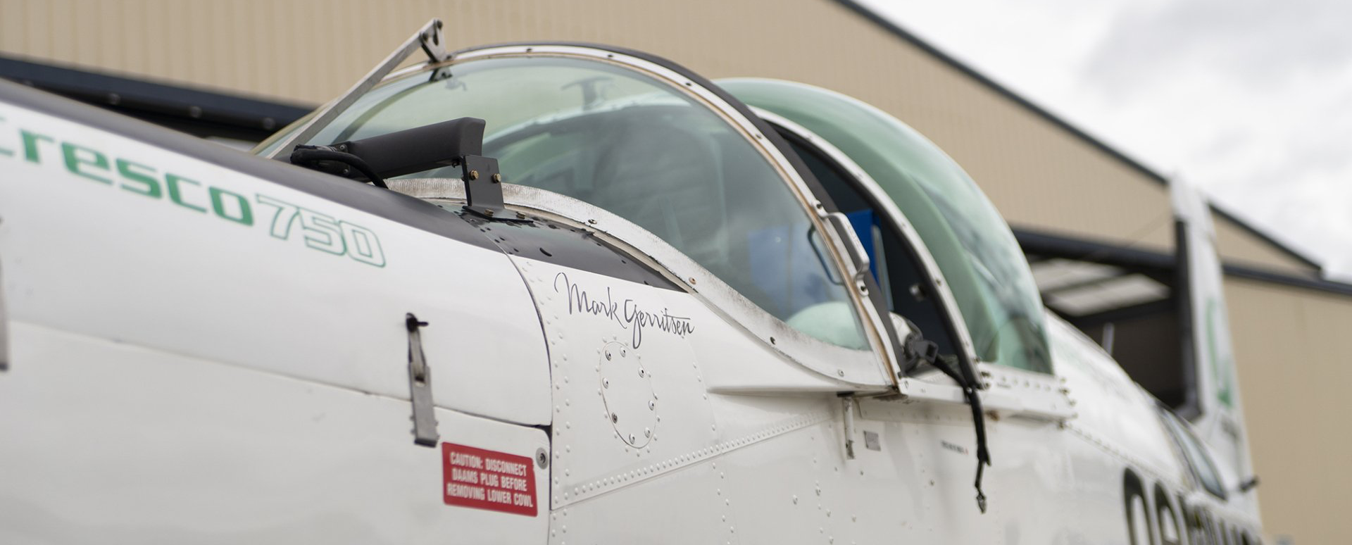
Ravensdown partnered with Beta Solutions to develop a highly specialised Lightbar display, which is now used to guide Aerowork pilots during aerial topdressing operations. Aerowork is the largest aerial fertiliser applicator in New Zealand, and with a history stretching back over 60 years, it is also the most experienced aerial spreader in New Zealand. Its pilots spend thousands of hours topdressing farmers' fields with 100,000 - 200,000 tonnes of fertiliser every year [1]. The development of this custom avionics tool was part of Ravensdown's continuous effort to improve the safety and effectiveness of its application operations.
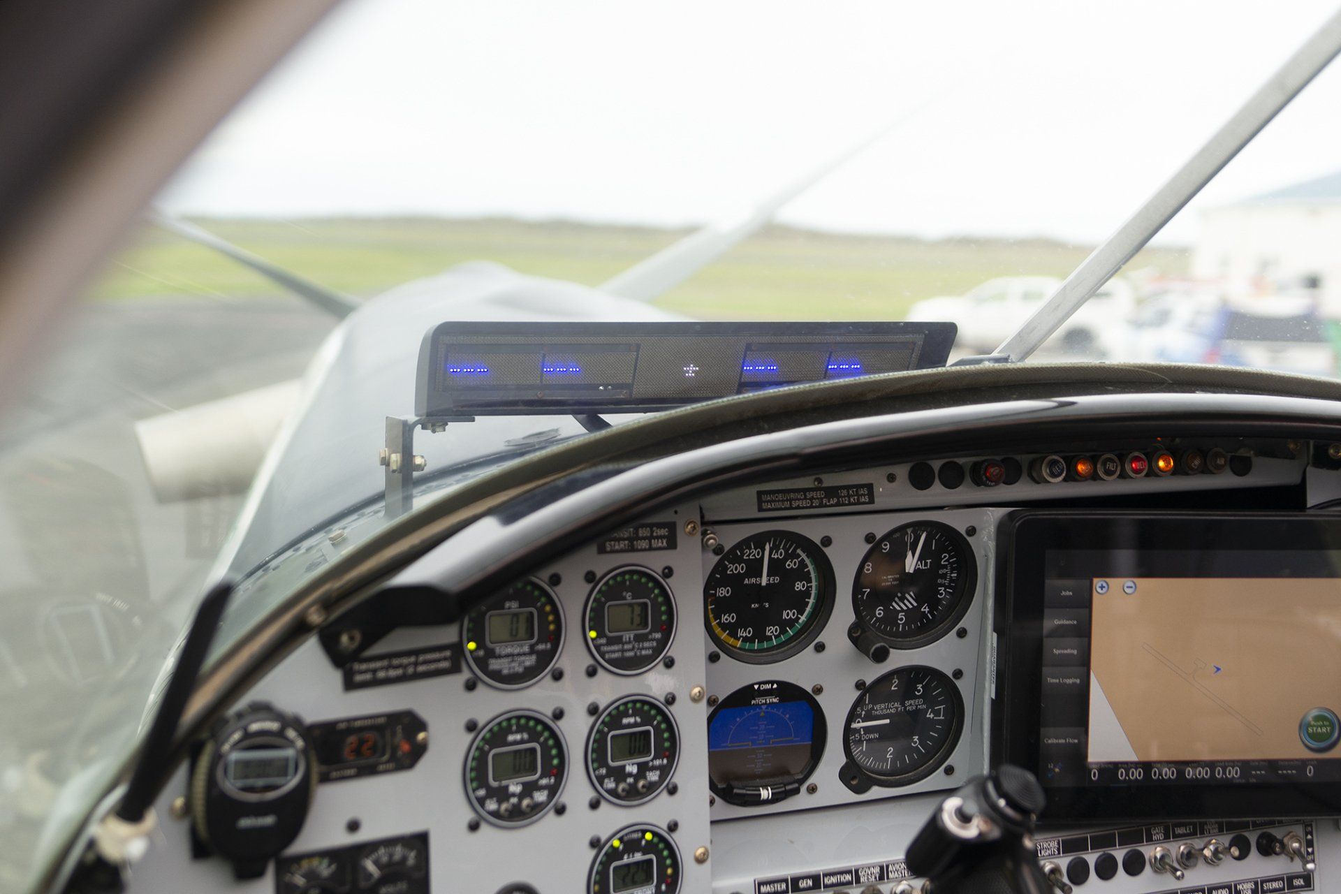
With the Lightbar, strings of RGB LEDs illuminate left-to-right to help guide the pilot along predetermined swathe spacings, while five high density 2D LED arrays display other critical flight information. The Lightbar is mounted outside the cockpit, so that it is in the optimal position in the pilot's field of view - enabling the pilot to be guided with only quick glances.
There were several engineering challenges, which were overcome to develop this avionics tool. These are discussed in the Electronics, Enclosure, and Firmware development sections below.

Electronics Development
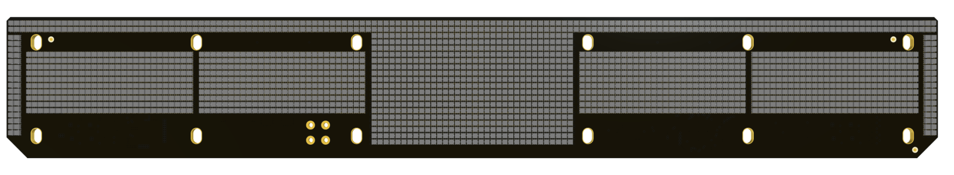
Figure 1: CAD rendering of the Lightbar LCD display.
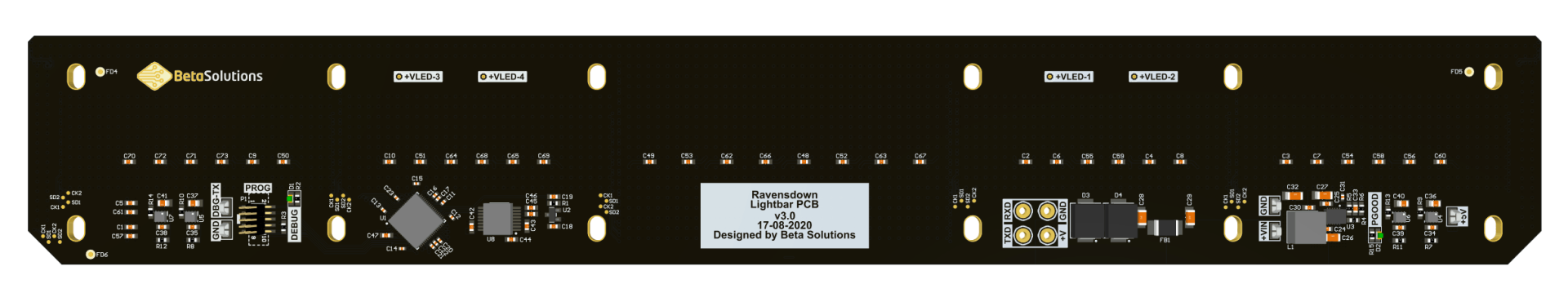
Figure 2: CAD rendering of the Lightbar PCB.
The display electronics are composed of five individual LCDs and five strings of RGB LEDs. These parts, along with some ambient light sensors, are mounted on one side of a circuit board (Figure 1), where the pilot can see it.
Mounted on the other side of the circuit board are the additional electronics, which support the operation of the displays (Figure 2). These key functional sections are:
- Microprocessor - This is a small digital computer, which is programmed with firmware (a.k.a. "embedded software"), which overall controls the system.
- Power Supplies - These provide all the various voltages that are required to power different parts of the system.
- Input Protection - The power supplies were designed to be extremely robust to external transients and other unwanted inputs.
- Serial Transceiver - This enables robust communication with the Ravensdown Tablet computer within the cockpit.
All of the hardware was designed using industry-standard 'best practices', ensuring the quality of the product. Some of these practices were as follows:
- Design for manufacturing
- Selecting components with excellent supply chains - It's critical that stock can be procured reliably for years.
- Optimising the design for automated fabrication and assembly - This means we can fully leverage the efficiency of the manufacturer's highly automated systems.
- Test points for important signals - For automated testing.
- Protection and signal conditioning for all inputs and outputs - This ensures the Lightbar will operate reliably for many years even in harsh conditions.
- High-quality connector selection and cable strain relief - Connectors and cables can be a significant source of unit failures if not correctly designed.
- Design for rejection and suppression of Electro-Magnetic Interference (EMI) - This ensures that the operation of the Lightbar does not interfere with the other aircraft avionic systems.
- Design Validation - Once the hardware design has been finalized it must then be validated to ensure it operates as intended. Typically this involves making a complete prototype and running it through a myriad of tests to prove compliance with the specifications.
The most challenging aspect of the electronics design was selecting a display, which could meet all the tough environmental conditions experienced, when mounted on the outside of a plane. The Lightbar is exposed to direct sunlight, which can have a brightness of up to 120,000 lux. Most display technologies struggle to be readable in those conditions because the sunlight washes out the light from the displays. We selected a display which had a brightness of 450 nits and then modified the LCD controller to enable operation up to 800 nits - while still ensuring the screen remained within its design limits. The ambient light sensors were used to intelligently control the brightness of the screens, so that they only operate at maximum brightness, when in direct sunlight. This helps to extend the life of the displays, by reducing their power consumption and therefore reducing the temperature at which they operate.
Enclosure Development
The enclosure design was critical to the success of the project. The sensitive display electronics had to be protected against the hot sun, driving rain, and a "wind" of over 120 knots, as the aircraft manoeuvres through the skies. Therefore, the following design considerations were given:
- Aerodynamics
- The Lightbar was designed to be aerodynamic, so as not to induce undue drag on the plane. This involved designing the enclosure to be sleek and as low-profile as possible. Additionally, vortex generators were also added to the top lip to reduce the effective drag.
- Viewability
- Direct sunlight on the LCD would have significantly reduced the 'viewability' of the display. Therefore, the enclosure was designed with a visor to block as much direct light as possible - ensuring the display was always in shadow - promoting good contrast for the bright screens.
- Indirect sunlight and reflections were also a potential problem, as the glare and reflections could prevent good viewing. To solve this problem, a special 'low-glare' acrylic material was selected and tested - which ultimately significantly improved the viewability. Incidentally, this same material is used in art galleries to reduce glare and reflections.
- Water Ingress
- Of course, these aircraft fly in wet conditions too. Therefore, the enclosure also had to protect the electronics from any water ingress. Keeping water out when the enclosure is being blasted by 210+ kph winds is no trivial matter. Careful design and selection of appropriate seals and membranes were essential.
- Conformal coating of the electronics also provided extra resistance to moisture as well as vibration.
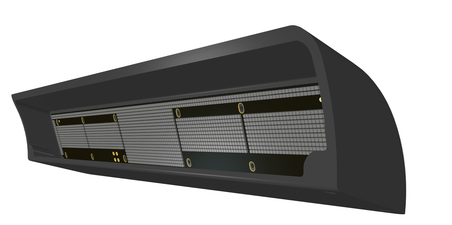
Figure 3: CAD rendering of the side view of the Lightbar enclosure.
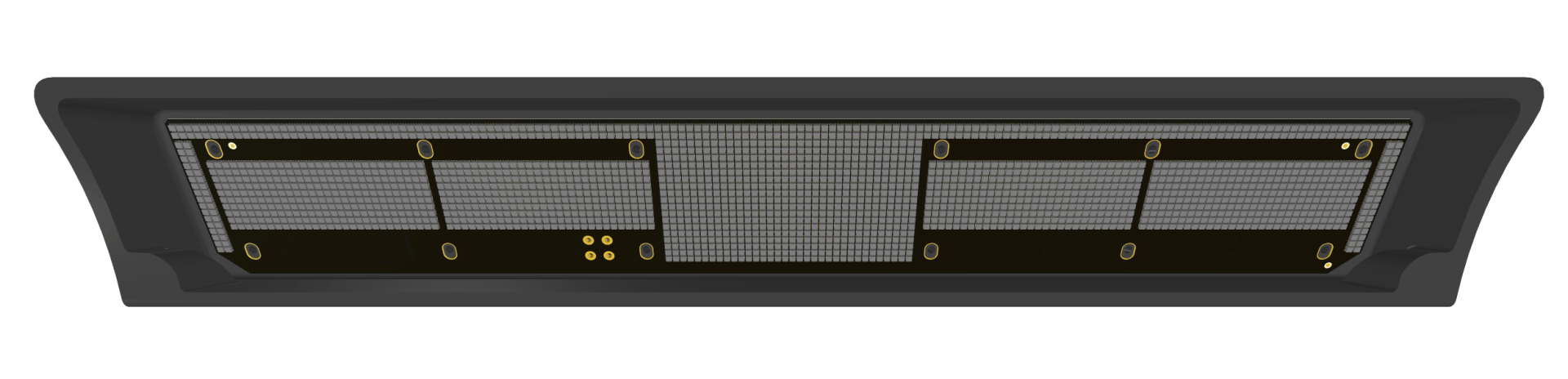
Figure 4: CAD rendering of the front view of the Lightbar enclosure.
Firmware Development
Overall Functionality:
Firmware is the "brains" of most embedded systems and this project was no exception. Essentially, the firmware was responsible for the following aspects:
- Low-level control of the peripheral hardware electronics - such as LEDs, LCDs and light sensor readings etc.
- Acting as an interface between the Ravensdown computer Tablet (in the cockpit) and the peripheral electronics.
Communications:
As mentioned previously, Ravensdown utilises a computer (Tablet) within the cockpit. High-level custom written software running on this Tablet monitors and calculates real time data, such as the aircraft's position and exactly where, and how much, fertiliser is to be applied.
Therefore, it was essential that the Tablet software could seamlessly communicate with the Lightbar - updating the Lightbar's LEDs and Screens with current data.
This communication was accomplished through serial UART, which abstracted the complexity away from the software.
Bootloader:
As often with any product, additional features may be required in the future and Ravensdown also required the ability to update the firmware using the Tablet - even while the Lightbar remained on the plane. The solution was to write a second piece of firmware called a bootloader, which is able to use the same UART communication with the Tablet to update the application firmware, without the need of a dedicated programming cable. We also developed a software program to run on the Tablet to update the Lightbar’s firmware.
Best Practice:
Our standard practice, for a project of medium complexity such as this one, is to use a Unified Modelling Language (UML) event-based State Machine operating system. A real-time operating system (RTOS) was utilised - bringing the following benefits:
- It was already well tested and could be relied on fully.
- The Application code was designed in a visual way and the state-machine architecture allowed for easier understanding of the program's operation.
- The Firmware was more easily maintainable, as the developer could easily see what the code was doing (at a high level) very quickly.
- It simplified the overall design and consequently improved the firmware stability.
Additionally, we implemented our other standard firmware design practices - which included:
- Implementing a watchdog timer - This is a safety feature that ensures that firmware doesn’t lock up.
- Resetting the firmware at least once a day - This 'fresh-start' ensures the firmware is always in a known good state.
- Using CRC error checking on every communication packet - Essentially eliminating the probability of corrupt packets being misinterpreted.
- Using a a firmware versioning system - For storing code and tracking firmware changes during development.
Testing and Validation
It is almost always more cost-effective (in the long run) to invest in designing any product "right" the first time, rather than releasing inadequately tested products to the market, only to experience product failures at a later date.
It was important to both Ravensdown and us to undertake thorough design validation testing before the Lightbar was installed in an aircraft. This involved:
- First validating the design integrated into a complete benchtop system - running a testing software script. The benchtop controller ran simulated swathe runs with data collected from actual historical flights, to validate "normal expected operation".
- As well as simulating "normal" operation, the testing script also included simulating faulty commands, and loss of communication, to ensure the Lightbar could handle such events, should they occur out in the field.
- The system was then installed on the bonnet of a ute for final validation before being installed on an aircraft.
Success
Beta Solutions is proud to have successfully met Ravensdown's original goal of transforming its concept idea into a commercial product. Aerowork pilots are very happy with the Lightbar product, and it is now an essential part of their daily top-dressing operations.
Client Testimonial
"Ravensdown took on the challenge of developing a state-of-the-art aerial spreading control solution, to deliver improved fertiliser application in New Zealand. We came to Beta Solutions Ltd with several technology hurdles, one of which was an avionics lightbar capable of displaying a significant amount of complex information, in a simple and effective way. The highly skilled team at Beta Solutions worked with Ravendown and our Aerowork pilots, to overcome the unique technology challenges presented by our operating environment, and delivered a solution specifically tailored to our needs."
Dr. Rob Murray - Ravensdown Technology Innovation Manager
References
[1] 2010, M.C.E. Grafton. A Massey Univerity PhD Thesis titled: 'Flow of Particulate Material From a Topdressing Aircraft' Retrieved from
https://mro.massey.ac.nz/bitstream/handle/10179/1956/02_whole.pdf
[2] https://www.ravensdown.co.nz/services/spreading/aerowork-aerial-spreading
* All the content in this article, including imagery, has been approved by our client for publication on this website.