

Things To Know About Lightning Strikes & Electronics Design
Date: April 29, 2021
Introduction
In the real world, electronics can be subject to all sorts of nasty electromagnetic events. These 'transient' events could damage or destroy devices unless careful consideration has been given in the design stage to integrating protections. Large transient energies caused by lightning strikes (aka surges), electrostatic discharge (aka ESD), Electrical Fast Transients (EFT), and other electromagnetic phenomenon including can all damage electronic devices. These energies can be introduced through ports or anywhere a user can physically touch the electronic device.
Devices which have been damaged by environmental transients are often difficult to diagnose in the field. The device may appear to have stopped working or it may exhibit erratic behaviour.
The measure of a device's robustness to transients is it’s Electro-Magnetic Compatibility (EMC). This is a measure of how a device interacts with it's electromagnetic environment, and with other equipment. Most markets legally require that your device be EMC tested in a lab to prove it is compliant with their EMC requirements before it can be sold. Failing this testing is expensive as this requires redesign and retesting late in the project.
Many EMC problems are not simple or obvious, so they must be considered at the start of the product design. Leaving these considerations to the end of the design cycle can lead to overruns in the engineering budget and schedule.
See our previous article on compliance for more general EMC information - Electromagnetic Compatibility (EMC) Compliance - Answers to Frequently Asked Questions.
This article specifically addresses how lightning induced transients (surges) can damage your device even if there was no ‘direct’ strike.
How Lightning Damages Electronic Devices
Direct Strikes
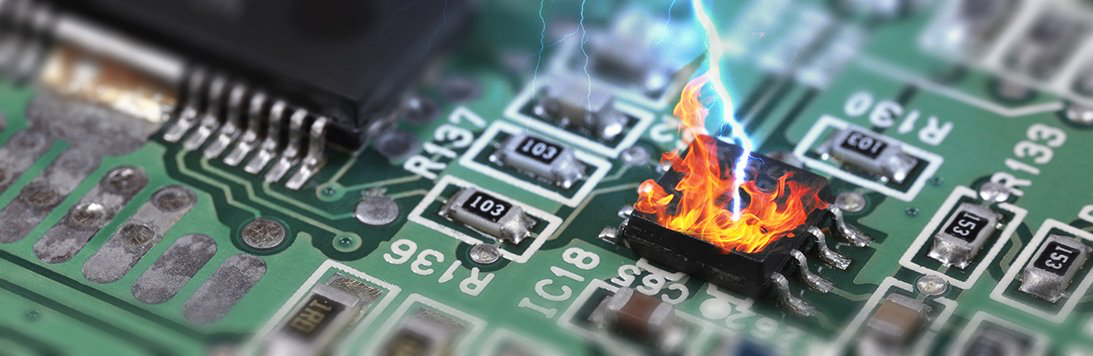
The most obvious way in which lightning destroys electronic devices is, of course, by a direct strike. These will almost vaporize anything and as such there aren’t many practical ways that a device could be protected from it.
The image below shows a household electrical distribution box which has been destroyed by a direct strike.
Figure 1: A household electrical distribution box which has been destroyed by a direct lightning strike.
Indirect Strikes
Thankfully direct Strikes are very uncommon but there are also indirect effects from nearby lightning strikes which can still wreak havoc. It is actually possible to protect against the damage these indirect effects can cause as their energy is magnitudes lower than a direct strike.
These indirect effects are much more common than direct strikes because the effective radius of a lightning strike is so much larger than the small area the lightning directly strikes. A strike could indirectly damage electronics even hundreds of meters away.
The image below shows a product’s circuit board/PCB which had components partially vaporized by indirect lightning effects. There’s a damaged shield bonding capacitor (these are normally rated for 1-2kV) and a damaged ethernet transceiver IC. The pressure from the chip being vaporised internally was enough to blow off part of the encapsulation compound!
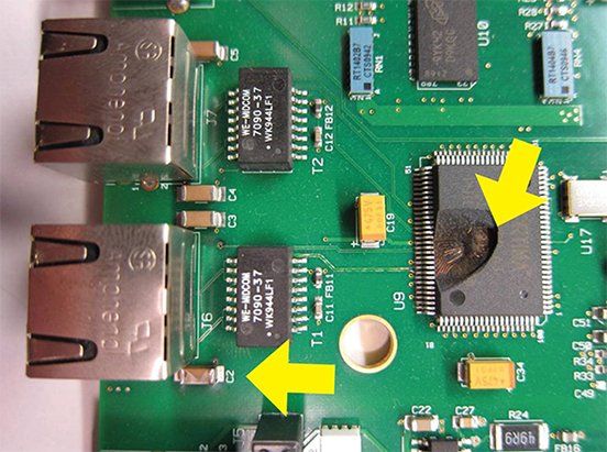
Figure 2: An example of a product which had components partially vaporized by indirect lightning effects.
The effective radius of a strike can be hundreds of meters because of the incredible power that they contain. The average lightning strike contains, on average, approximately 1 billion joules of energy. This sounds like a lot of energy but, to give this some perspective, this is ‘only’ enough energy to boil ~24 cups of coffee. Lightning is so destructive because this modest amount of energy is delivered in just milliseconds or even microseconds. 1 billion joules over 1 millisecond is
1 trillion watts of power.
Even just a small portion of this energy coupled into a device is enough to cause damage.
There are two mechanisms that allow energy from a strike to couple into a device indirectly. These are:
- Near and far field electromagnetic coupling
- Ground potential gradient coupling
Near-Field and Far-field Electromagnetic Coupling
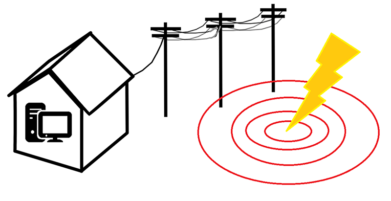
Figure 3: Graphic illustration of electromagnetic pulses propagating outwards from a lightning strike.
The incredible voltages and currents of lightning strikes produces electromagnetic pulses (EMPs) which propagate outwards (at the speed of light) in electromagnetic waves. The magnitude of these waves can be so high that they couple or induce significant current and energy into nearby conductors (e.g. power lines or communication cables). The coupled current can be on the order of hundreds to thousands of amps.
There are two simple factors which gauge how much energy is transferred:
- The proximity to the lightning strike (EMP source) - The intensity of the EMP pulse adheres to the inverse square law with respect to distance from the strike. Intensity = 1/(Distance^2). I.E. the intensity of the EMP quickly drops off the further away the strike is.
- The length of the cable run - Generally the amount of energy transferred is a function of how long the cable run is that is exposed to the EMP. As a rule of thumb, cable runs longer than 10 meters may be susceptible [1].
It’s important to note that buildings and the materials they’re made from do little to impede or attenuate EMPs. Cable runs are almost as susceptible inside as they are outside. Dangerous energy can couple in regardless.
Ground Potential Gradient Coupling
This coupling mechanism works through the interaction of lightning strikes and the earth (e.g. dirt, soil, etc.) around impact points.
Soil has a finite resistance and therefore the earth is literally a giant resistor. The current from the strike on earth travels outwards from that point. This current produces voltage potentials in the earth's surface as it travels out that then drops off in magnitude as the current spreads out and the current density reduces. Ohm's law states that where there is current flowing through a resistive material that there must also be a voltage potential. For example - the voltage potential between two points on the earth, in proximity to a strike, could be tens of thousands of voltages different due to the charge flowing through the ground.
Systems which have multiple connections to earth (in different locations) can be susceptible to energy coupling through those grounding points from ground potential gradients induced by lightning currents.
One example of a common system which can be susceptible to this coupling mechanism is an ethernet cable that spans from one building to another building (e.g. the network of a university campus). Each of these buildings will have their own ground rod dug into the earth which the neutral and earth conductors of the building's wiring system are tied to. Therefore the electrical devices in that building are roughly at the same potential as the building’s earth rod. During the instance of a lighting strike in close proximity, these two buildings could be at potentials thousands or tens of thousands of volts different. This might not otherwise have been an issue if it wasn’t for the ethernet cable that connects the two buildings together. This cable would have equipment at either end which are at very different voltages. Ethernet is normally designed to be robust to these events through galvanic isolation, but it will still fail if the voltage potential is great enough to breakdown the isolation.
The image below illustrates this coupling mechanism.
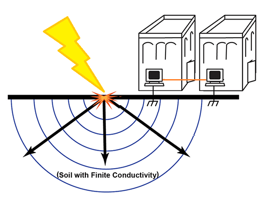
Figure 4: Graphic illustration of ground potential gradient coupling.
Some ways that electronic products can be designed to be robust to transients
There are various components that designers can choose to protect their electronic products from lightning surges. The exact method implemented and which protection components are selected depends on the project and technical constraints.
Here are several categories of transient protection components which a designer can pick and choose from.
Transient Voltage Suppression (TVS) Components
TVSs are semiconductor devices designed to provide protection against transients by limiting voltage. They are designed to operate in the Avalanche mode and essentially clamp to a set voltage threshold.
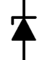
- TVS diode - TVS’s can be used to protect high speed data lines as they can have low capacitance. They’re also extremely fast so can react and protect for transients on the order of nanoseconds.

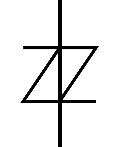
- Zener Diode - Low cost and have a stable steady state voltage when reverse biased.
- Metal Oxide Varistor (MOV) - Can absorb high energy transients and operate in ~1nS but have a high capacitance.

Crowbar Components
Crowbar devices conduct when the voltage over them reaches a threshold which causes them to trigger to an on-state. In this state the crowbar devices limits the voltage all the way down to approximately zero. Almost like a metal crowbar was placed across the conductors (hence the name)!
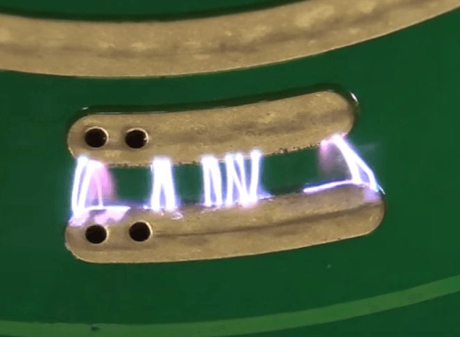
- Gas Discharge Tube (GDT) - is a sealed device containing a special gas mixture trapped between two electrodes, which conducts electric current after becoming ionized by a high voltage spike. These devices are often rated to shunt thousands of amps. GDTs are much slower than TVSs as they take ~1uS to engage. This makes them less useful for protecting from ESD but they’re great for absorbing surge transients.

- PCB Spark Gap
- A transient protection feature can be designed into the PCB itself. Making this a 'zero' cost solution for diverting transients safely to ground. Normally a PCB spark gap consists of two copper traces separated by a small gap with no solder mask. High voltage transients can jump this gap but it does not conduct during normal operation. The main drawback is that the designer does not have much control on performance and the performance can degrade with time and environment.
- Thyristor
- A crowbar type thyristor is triggered into a low impedance state when the voltage across its terminals reach a certain voltage threshold. It then resets back into a high-impedance state once the transient current subsides and reduces below a threshold.
Protection by Galvanic Isolation
This is just a fancy way of saying that there is an ‘air-gap’ in the device or port which prevents a transient surge from being able to conduct to/from earth.
Galvanic isolation protects devices because transients' currents are prevented from ever entering the electronic device. Electricity can’t directly jump the gap without significant potential.
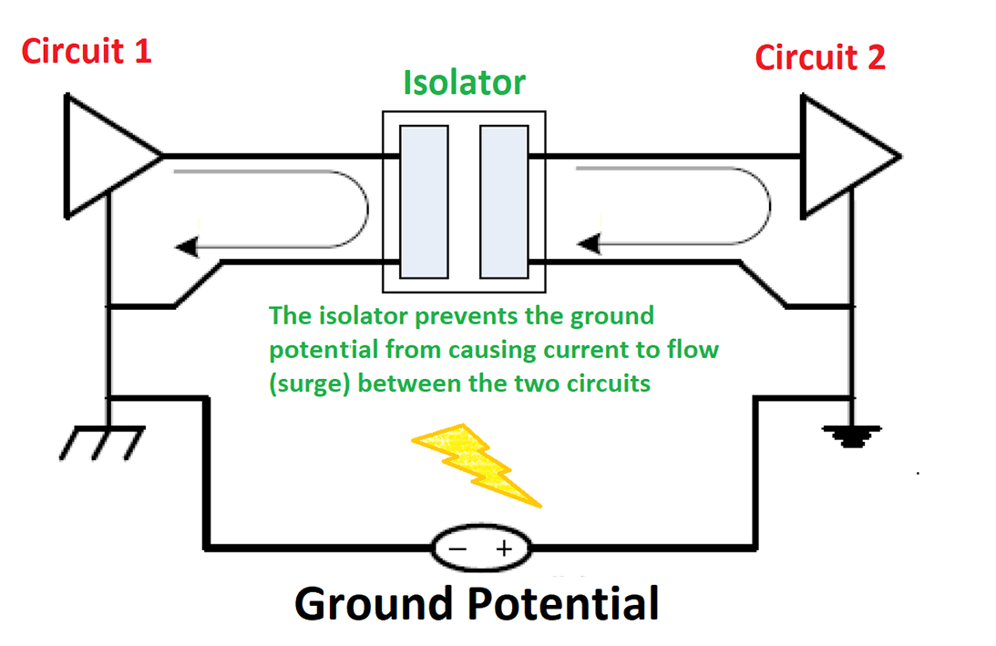
Figure 5: Graphic illustration of an isolation component preventing current from flowing during a ground potential transient.
Here are a few examples of common components which designers use to galvanically isolate power or data ports:
- Transformer - Whereby power and/or data is sent over galvanic isolation by being converted to magnetic field flux by a coil, which is then passed through the transformers core and then converted back to electricity by another coil.
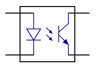
- Optocoupler - Whereby data is sent over galvanic isolation by being converted to photons by a light emitting diode (LED) and then converted back to an electrical signal by a transistor. There are optocouplers that can be used to transfer power but this is more of a niche application.
Other Transient Protection Devices
- Transient Blocking Unit (TBU) - circuit protection devices that block transients using a current disconnecting mechanism rather than diverting or shunting the surge to ground. These devices are triggered by high currents and work to limit current going into a device. TBUs are often used in conjunction with a component which can divert or shunt the transient current to ground.
Example RS485 Communication Bus Protection
The design below demonstrates how a designer might go about protecting a RS485 transceiver which could be attached to hundreds of meters of cable. The solution is robust to high high energy surge, EFT, and ESD transients.
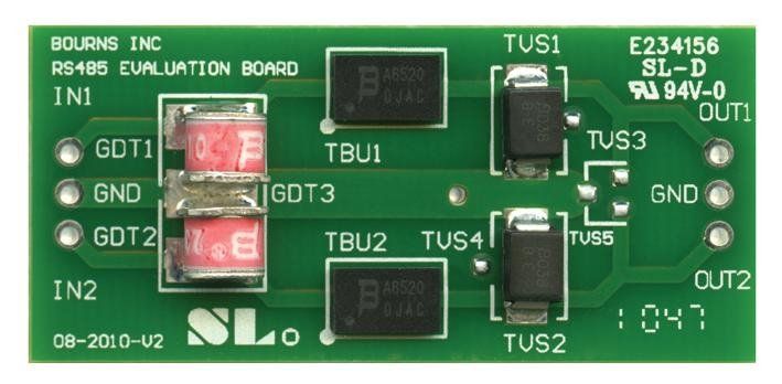
Figure 6: Image of RS485 protection components on a Bourns development board. [2]
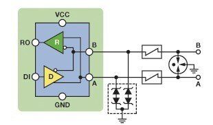
Figure 7: Symbolic representation of the above PCB design. [3]
The circuit design was designed with three different transient protection components:
- Gas Discharge Tube (GDT)
- This is used to crowbar/divert the <5kA currents from any induced surges on the RS485 bus.
- Though it is not fast enough to suppress ESD or EFT transients.
- It requires 150V to trigger.
- Transient Blocking Unit (TBU)
- This is used to help ensure the GDT can be triggered so it clamps during a surge.
- These components trigger and limit the current to just 100mA in ~1uS.
- They can limit current up to a voltage of 650V. Though the GDT will trigger before this.
- TVS Diodes
- These are used to suppress nanosecond transient like ESD and EFT events.
- They also limit the voltage on the RS485 bus during a surge by diverting the 100mA let through by the TBU to ground.
RS485 transceivers are inherently tolerant to -7/+12V inputs, hence the choice of these TVS values are just above these values.
These parts all work in unison to make the RS485 bus incredibly robust to almost any transient which in turn improves reliability.
Conclusion
A designer can only hope to protect their electronic product until they have gained a fundamental understanding of the principles by which transients can be generated and damage their designs.
Lightning strikes can damage devices even if they do not experience a direct strike. The potential damage radius of a lightning strike can be hundreds of meters.
Designing for lightning and other high-voltage electrical transients can seem like a daunting task at first, but there are common, conventional, and proven methods for protecting electronic circuits from these events.
At Beta Solutions, our experienced electronics hardware engineers have the skill and proven track record to use the best suited design methodology to protect our clients' products from the transients they may ever experience. You can get in touch with us to discuss any idea you have in mind, or a problem you may need solved, via our contact page or give us a call.
References
- Referenced from https://blog.se.com/power-management-metering-monitoring-power-quality/2013/05/08/length-the-critical-parameter-in-installing-surge-arresters/
- Image retrieved from https://www.analog.com/en/analog-dialogue/articles/safeguard-your-rs-485-communication-networks.html
- Image retrieved from https://my.element14.com/bourns/rs-485evalboard1/eval-board-for-rs485-port-protectn/dp/1871188
- https://www.edn.com/avionics-lightning-protection-design-gui/
- https://www.researchgate.net/publication/329606919_Techniques_to_Design_Robust_Lightning_Protection_Circuits_for_Avionics_Equipment
- https://www.analog.com/en/analog-dialogue/articles/safeguard-your-rs-485-communication-networks.html
- https://www.electronicdesign.com/industrial-automation/article/21808086/protect-rs485-transceivers-from-electrical-surgesand-maintain-signal-integrity
- https://www.analog.com/en/technical-articles/rs-485-communication-link-vs-the-electric-fence.html
- https://www.ti.com/lit/pdf/TIDUCY9A
- https://strikecheck.com/webinars/surge-and-lightning-damage-to-electronics/
- https://incompliancemag.com/article/designing-ethernet-cable-ports-to-withstand-lightning-surges/
- http://ww1.microchip.com/downloads/en/DeviceDoc/EMC Newsletter Issue 5.pdf
- Figure 1: Image retrieved from https://strikecheck.com/webinars/surge-and-lightning-damage-to-electronics/
- Figure 2: Image retrieved from - https://incompliancemag.com/article/designing-ethernet-cable-ports-to-withstand-lightning-surges/
- PCB Image used in Banner - Image by <a href="https://pixabay.com/users/nanoslavic-17278421/?utm_source=link-attribution&utm_medium=referral&utm_campaign=image&utm_content=5431664"nanoslavic</a>> from <a href="https://pixabay.com/?utm_source=link-attribution&utm_medium=referral&utm_campaign=image&utm_content=5431664"Pixabay</a>>